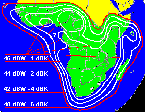
Satellite downlink EIRP
Referring to the satellite transmit downlink coverage pattern, the saturated EIRP on each contour will be specified in units of dBW. For example +45 dBW in the area of the beam centre and +42 dBW at the -3 dB contour. The figures given refers to a whole transponder. Note the bandwidth, for example, 36 MHz.

This image shows four EIRP contour levels each with saturated dBW for the downlink.
( The dBK figures refer to the uplink G/T. )
If a transponder is operated with a single carrier the carrier power will be adjusted to the saturated power, or perhaps -0.5dB to -1 dB lower to minimise distortion and make advanced modulation methods such as 8QAM, 16QAM and 32APSK work better.
For multi-carrier operation you might conservatively assume a multi-carrier transponder operating point of -10dB input back off and -4.5dB output back off, the operating downlink EIRP, on the -3 dB contour will be +45 -3 -4.5 = +37.5 dBW. This refers to the whole transponder output power and is the aggregate of all the multiple small carriers present.
Some satellite transponders have superior output power amplifiers and/or linearisers which enable multi-carrier operation nearer to saturation as the -4.5dB output back off mentioned above represents a serious loss of power. Ask the satellite operator for a graph of input and output backoff with the carrier/intermod ratio also shown. The satellite operator will normally decide for themselves what transponder back offs are to be used when there are multiple customers, each renting some fraction of the transponder.
For a leased 2 MHz slot, out of a transponder bandwidth of 36 MHz, the available downlink EIRP will be +37.5 -10 log(36/2) = +25 dBW . This assumes that the total power is more or less evenly divided according to bandwidth. In practice you can buy more power if you need a high power spectral density carrier, but on average other people will have to have lower power per unit bandwidth to keep the total operating point under control.
Good background reading to download and read later: An 87 page pdf file from the ITU about link budget calculations.
You could buy say 2 MHz bandwidth and the matching +25 dBW of power and then, as an extreme, concentrate all the +25 dBW into a narrow carrier of say 250kHz bandwidth, while leaving 1.75 MHz of your bandwidth unused. You might do better to broaden your carrier with as much more error correction bits as possible. High density carriers cause interference and may exceed limits, so moderation is recommended. Don't transmit high power un-modulated CW carriers.
So put 25 dBW into the link budget for the downlink EIRP for a 2 MHz bandwidth model.
If you have come from the link budget page, you can go back to it and not lose any figures you have inserted by clicking on the BACK button now. Return to the satellite link budget with figures deleted.
|
► Page started: 2015. Amended 28 July 2024, 2025-03-02 Copyright Satellite Signals Limited © 2015 all rights reserved. |