Satellite Internet Forum.
Welcome, Guest. Forum rules.To search this site click here > SATSIG search
| Home Login Register |
| › Recent Posts |
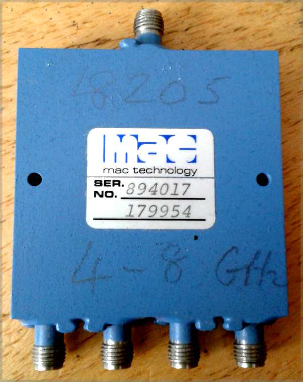
| 1 | VSAT technology and installation / Hub and VSAT satellite equipment for sale and wanted / For sale: MAC Technology 4-Way Power Divider, 4-8 GHz SMA connectors on: Yesterday at 3:44pm |
||
|
|
|||
| 2 | Anything else / General and other topics / Re: Satellite communications and Artificial Intelligence on: Feb 21st, 2026 at 12:55pm |
||
|
|
|||
These are the top three pages reported by Bing "AI Performance. Citation sources: Microsoft Copilots and Partners" 1. Shows aerial photos of property address 2. About low noise block (LNB) converter 3. List showing how many geostationary satellites are there in orbit The top one (1) simply uses Google Maps API to give you an aerial view of your house, with an option for terrain height information. If you want satellite dish pointing data for your area you are better going to my maps index page https://www.satsig.net/maps/ and picking a page that covers your general country or location. The two other pages (2) and (3) are satellite communications related. If you find any errors in these pages, please tell me. |
|||
| 3 | Anything else / General and other topics / Re: Satellite communications and Artificial Intelligence on: Feb 19th, 2026 at 6:37pm |
||
|
|
|||
Just a reminder... According a report from Microsoft Bing, during the past three months, 137 pages from this web site have been cited in AI outputs. Total number of occasions = 9527 This report gives me mixed feelings. First, I am delighted that AI finds the site's content of interest. Second, it make me realise how important it is that the site content is factually correct. All the regular content .htm type web pages are my creation and are not AI generated. I can't say for certain however regarding content in these forum pages. Of the total of 136 pages, 18 are from this forum and I will be slowly going through them, editing to improve clarity, check that any links work and that links go to useful places. Since you, as a visitor, may have knowledge of satellite communications please provide me with feedback if you find any errors. Please say the page url and explain what is wrong and provide your suggested correction. Email me at eric@satsig.net Best regards, Eric. |
|||
| 4 | Anything else / General and other topics / Re: Understanding Antenna Standing Wave Ratio (SWR) on: Feb 8th, 2026 at 8:31pm |
||
|
|
|||
The above posting about VSWR reminds me of an experience I had connecting high power amplifiers with rectangular waveguide output to an antenna which had rectangular waveguide inputs. For the cross site connection, I was supplied with a very long length of Andrew HELIAX ellipti-guide which was elliptical corrugated copper tube waveguide with a black outer sheath. I was also given two rectangular to elliptical waveguide adaptors to go at either end. 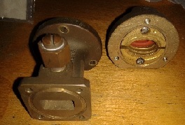 Illustrated: Ellipti-guide adaptor. These waveguide adaptors each had 3 small tuning screws intended to improve the VSWR across the elliptical to rectangular transitions. The image above shows a pressure dry air connector. The 3 tuning screws are underneath. I wondered how to make these adjustments. Starting at the HPA, I installed a high loss (-40 dB) cross waveguide coupler at the end of the rectangular guide with the coupling direction facing backwards to the intended power flow. 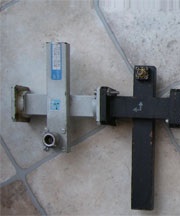 Illustrated: Two Ku band cross-waveguide couplers. So, when power was going from the HPA (rect) to the ellipti-guide any power coming out the side arm would relate to the reflected component from the antenna and backwards towards the HPA. This worked well and I was able to take measurements across the intended 14-14.5 GHz frequency range and adjust the screws for minimum reflections. While this was going on, the antenna end of the long cross site ellipti-guide was terminated in a dummy load. The process was then repeated at the waveguide transition at antenna end with the antenna connected, with emphases on very low power and the dish pointed safely away from the geo orbit. Measurements were done with sensitive spectrum analyser. If you try anything like this take care. The microwave HPA output is hazardous. Hazard to yourself (mainly your eyes) Hazard to the satellite (interference) Hazard to your test equipment (burning out expensive spec an or sensors) If you are connecting a spectrum analyser or power meter to the side arm of the cross-waveguide coupler do the calculations first and check that the levels into the meter will be acceptable. e.g. 400W forward power, 40 dB cross waveguide power monitor point in the forward direction. 400W = 26 dBW = 56 dBm Coupler loss = -40 dB So power to spec an or power sensor head = 56 - 40 = +16 dBm. See also here for microwave power measurement |
|||
| 5 | Anything else / General and other topics / Understanding Antenna Standing Wave Ratio (SWR) on: Feb 6th, 2026 at 3:17am |
||
|
|
|||
What is SWR? The Standing Wave Ratio (SWR) is a measure of how well an antenna is matched to the transmission line and the transmitter. When an RF signal travels along a transmission line and encounters a mismatch, some of the energy is reflected back, creating a standing wave. At points where the incident and reflected waves are in phase, their voltages add to form a maximum voltage, called the voltage antinode (Vmax). Where they are out of phase, the voltages subtract, forming a voltage node (Vmin). Other points along the line have voltages between these extremes. This resulting wave pattern is called a standing wave, and the SWR is defined as the ratio of the voltage at an antinode to that at a node: SWR=Vmin/Vmax In RF measurements, the SWR measured using a slotted line or other methods can be used to calculate the reflection coefficient and absorption coefficient of materials. 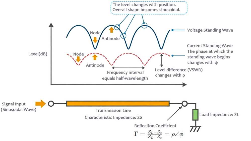 Why SWR Matters For RF systems, impedance matching is crucial. A low SWR ensures that most of the transmitted power is radiated by the antenna rather than reflected back to the transmitter. In broadband systems, SWR can vary across frequency, so the goal is to achieve good impedance matching across the entire operating range. Ideal SWR: SWR = 1 means perfect matching; all transmitted power is radiated, with no reflection. SWR > 1: Indicates some power is reflected back, potentially heating the feedline and, at high levels, damaging the transmitter. Common SWR Requirements and Measurement Typical targets: Mobile communications often require SWR < 1.5, while many applications aim for SWR < 2.0. Measurement tools: SWR meters, vector network analyzers (VNAs), or antenna analyzers are commonly used. Adjustment methods: Antenna tuning or matching networks can improve impedance matching and reduce SWR. 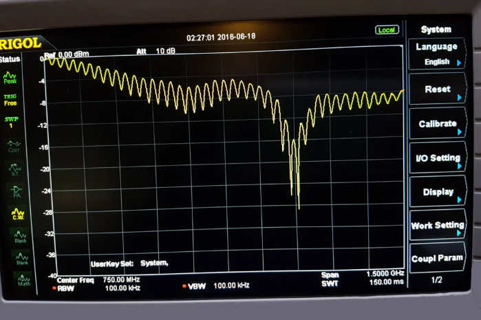 Why Do Standing Waves Form? Ideal case: If the transmitter output impedance, transmission line characteristic impedance, and antenna input impedance are all equal (typically 50Ω or 75Ω), all energy flows to the antenna with no reflection. Only a forward traveling waveexists on the feedline. Practical case: Antenna impedance varies with frequency, environment, and installation, making perfect matching difficult. Mismatch and reflection: When impedance is mismatched, part of the energy cannot be absorbed by the antenna and is reflected back toward the transmitter. Formation of standing waves: The reflected wave combines with the incident wave, creating points of maximum and minimum voltage along the line — the “standing wave.” SWR quantifies the severity of this mismatch and reflection. How to Calculate SWR SWR is often expressed as a ratio like 1.5:1 or 2:1 (usually we just say “SWR = 1.5”). Formula using reflection coefficient Γ: SWR=1+∣Γ∣/1−∣Γ∣ where ∣Γ∣ is the voltage reflection coefficient (ratio of reflected voltage to incident voltage), determined by how much the load impedance differs from the line impedance. Intuitive formula using impedances: SWR=Zload/Zline or Zline/Zload,take the larger value Example: If the feedline is 50Ω and the antenna is 100Ω, SWR = 100/50 = 2:1. If the antenna is 25Ω, SWR = 50/25 = 2:1. The further the impedance deviates from the line, the higher the SWR. How to Improve (Lower) SWR The key to improving SWR is improving impedance matching: Use a properly designed antenna: Ensure it operates well within the target frequency range. Use an antenna tuner: This device inserts a variable matching network between the transmitter and antenna, lowering the overall SWR on the feedline. Note: it does not change the antenna’s inherent SWR but protects the transmitter. Adjust antenna dimensions: For single-frequency antennas (like dipoles), fine-tune the element length to achieve resonance at the desired frequency, minimizing SWR. Ensure solid connections: Check connectors for tightness, oxidation, or moisture. Consider the installation environment: Keep antennas away from metal objects and walls and ensure sufficient height, as surroundings can significantly affect impedance. Summary SWR is a key “health indicator” of an antenna system, showing how efficiently energy is transmitted from the transmitter to the antenna. Low SWR means high energy transfer efficiency and a safe, stable system. Measuring and monitoring SWR is fundamental for any RF system, especially for transmitters. |
|||
| 6 | VSAT technology and installation / Hub and VSAT satellite equipment for sale and wanted / For sale: Hughes Jupiter SMC, LHCP and Modems on: Jan 20th, 2026 at 11:43am |
||
|
|
|||
For sale: Hughes Jupiter SMC, LHCP and Modems We have access to the following Hughes Jupiter inventory available for immediate sale: Qty 6 – Hughes Jupiter SMC (240 msybl) Qty 49 – Hughes Jupiter Modem HT2010 Qty 87 – Hughes Jupiter Modem HT2300 Qty 91 – Hughes Jupiter 2 LHCP 2.8 W Ka-Band Tx/Rx Outdoor Radios Sales, Satcom Solutions Inc. Cell: 732-810-9919 Skype: satcomsolutionsinc Web: https://satcomsolutions.org/ |
|||
| 7 | VSAT technology and installation / Hub and VSAT satellite equipment for sale and wanted / For sale: iDirect Evolution HUB hardware and line cards on: Jan 20th, 2026 at 11:42am |
||
|
|
|||
For sale: iDirect Evolution HUB equipment We currently have iDirect Evolution HUB equipment available, including XLC-11 and XLC-M line cards, as well as 15000-series HUB hardware, suitable for network expansion, redundancy, or spares. Sales, Satcom Solutions Inc. Cell: 732-810-9919 Skype: satcomsolutionsinc Web: https://satcomsolutions.org/ |
|||
| 8 | VSAT technology and installation / Hub and VSAT satellite equipment for sale and wanted / Wanted: 0.74m Antennas. Qty=100 on: Jan 20th, 2026 at 11:41am |
||
|
|
|||
Wanted: 0.74m Antennas by Skyware Global and resold by Hughes. Qty=100 All antennas are manufactured by Skyware Global and resold by Hughes, with the following part numbers of interest: .74 m Ku-Band – P/N 1500439-0016 .90 m Ku-Band – Antenna P/N 1506560-0031 Reflector: 1506560-0046 Az/El Mount: 1506561-0041 .98 m Ku-Band – P/Ns 1504178-0031 and 0800-3281 Satcom Solutions Inc. Cell: 732-810-9919 Skype: satcomsolutionsinc Web: https://satcomsolutions.org/ |
|||
| 9 | VSAT technology and installation / Dish pointing and alignment / Updated list of satellites and pointing angles etc on: Jan 2nd, 2026 at 6:54pm |
||
|
|
|||
 I have worked today to update the list of satellites used in all the dish pointing calculators etc. First I downloaded an up-to-date list of the 2 line elements for the geosats. Then converted then to orbit positions. Then updated all the relevant files on my server PC. List of satellites updated Legacy list of 2-line elements updated 2-line elements calculation updated Print out a list of all your visible satellites with az-el angles Please test these links. I hope they all work. Any problems, please email me at eric@satsig.net Best regards.. |
|||
| 10 | VSAT technology and installation / Satellite dish installations - pictures and descriptions / Re: Antenna Pointing Accuracy in Satellite Communication on: Dec 31st, 2025 at 2:42pm |
||
|
|
|||
I have added one of my antenna transmit pattern cuts below. 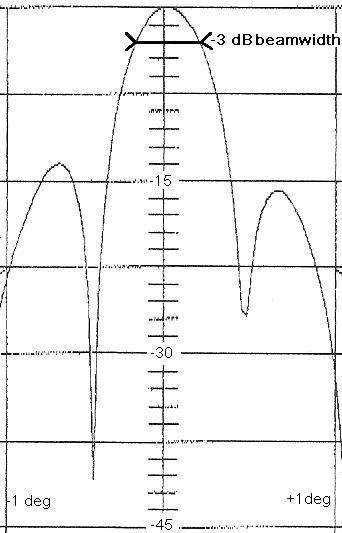 This image shows the recorded transmit antenna elevation pattern as the elevation angle of the dish was increased and the beam moved upwards across the satellite. The antenna was approx 7.5m diameter, transmit frequency approx 6.1 GHz. The recording starts on the left 1 deg below the beam centre and stops on the right 1 deg above beam centre. I have annotated the vertical scale to 1.5 dB per division to make it easy to identify the -3 dB level, shown as bold black line. The side to side, full -3 dB beamwidth is 0.4 deg. For interest, the first sidelobe (on the left of the display and thus this one is above the main beam) is about -13.5 dB down. The other sidelobe is -15.1 dB down. This plot was one of many pattern cuts. Not perfect sidelobe balance in the vertical plane yet, but fixable with several more steps by tilting the top of the subreflector by 1mm, either in or out, depending on whether it is a cassegrain or gregorian subreflector. A hint for anyone doing anything like this: Always record patterns with the antenna elevation going upwards or from left to right in azimuth (as viewed from behind the antenna) . You will than avoid confusion later when studying the plots. When you walk round to the front of the dish it is important to visualise where the high point of the first sidelobe ring is located. Read more here: https://www.satsig.net/sub-reflector-alignment.htm Antenna beamwidth calculator Here is a link to an antenna beamwidth calculator: https://www.satsig.net/pointing/antenna-beamwidth-calculator.htm Note that your results depend on the way the feed (and sub-reflector) distributes power across the dish surface. An evenly illuminated dish will give a narrow main beam but will have high (poor) sidelobe spill-over levels. The spill over increases noise from the ground. A tapered illumination with low levels at dish edge will have a wider main beam but low sidelobes and low noise from other satellites and the ground. Achieving required gain, noise temperature and simultaneous low sidelobes is a tricky compromise!. |
|||
Email me: eric@satsig.net
Powered by YaBB 2.5.2!
YaBB Forum Software © 2000-. All Rights Reserved.
Disclaimer, Terms of Use and Privacy Forum User Agreement Forum rules Cookie policy.
